
 EN
EN
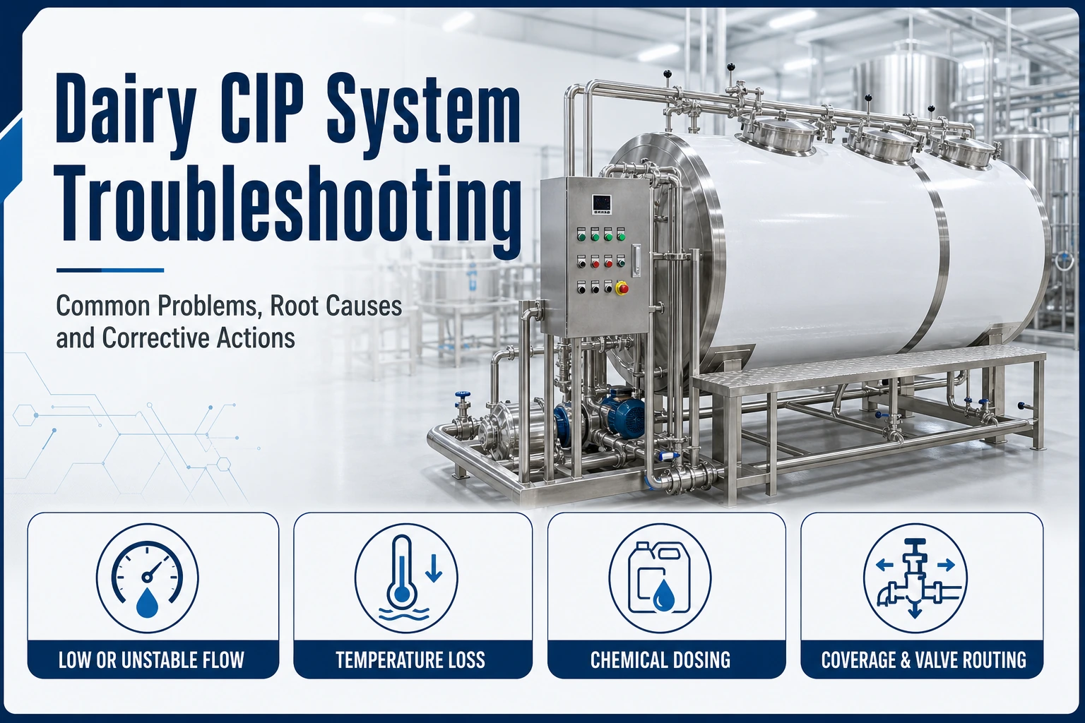
A dairy CIP system can finish every programmed step, display no alarm, and still leave product residue inside the processing line. The cause may be an unsuitable cleaning recipe, but it may also be insufficient flow, heat loss, inaccurate chemical dosing, poor tank coverage, incorrect valve routing, trapped liquid, or equipment that was never designed to clean effectively in place.
Successful dairy CIP system troubleshooting therefore begins with evidence, not with increasing every cleaning parameter. Raising temperature, extending time, or adding more chemical without identifying the real failure can increase water and energy consumption, damage seals or surfaces, delay production, and still leave the original problem unresolved.
In this guide, Weishu explains how dairy processors can move from a visible symptom to a structured root-cause investigation. The objective is to help production, sanitation, maintenance, and engineering teams determine whether the problem comes from the cleaning recipe, the CIP station, the connected equipment, the pipework, the control sequence, or day-to-day operation.
Why a Completed CIP Cycle Can Still Fail
A CIP program normally combines four cleaning actions: time, temperature, chemical action, and mechanical action. These factors work together. A longer cycle cannot fully compensate for a spray device that does not reach the upper tank wall. A correct chemical concentration at the CIP station does not prove that the same concentration reached the end of a long circuit. A pump running at its expected speed does not prove that every branch received the required flow.
The production equipment also forms part of the cleaning system. Tanks, pipe diameters, elevations, valves, heat exchangers, pumps, instruments, return lines, and drain points determine how the cleaning fluid moves. When a process line contains dead legs, air pockets, undrainable sections, shadowed surfaces, or incorrectly routed valves, the recipe may be unable to clean the entire product-contact area.
Before changing a recipe, answer three questions:
- Where is the residue or hygiene failure located?
- Which cleaning step should remove that specific soil?
- What evidence confirms that the required conditions reached that location?
These questions keep the investigation focused. They also separate a local equipment problem from a system-wide CIP problem.
Start With a Repeatable Troubleshooting Method
An effective investigation should preserve the failed condition long enough to collect useful evidence. If the line is immediately cleaned again using a stronger cycle, the plant may restore production but lose the information needed to prevent recurrence.
Define the Failure Precisely
“The line is not clean” is too broad. Record the exact symptom and location:
- visible protein, fat, mineral scale, color, or odor;
- failed rinse-water, surface, or microbiological check;
- residue inside a tank, valve, pipe, heat exchanger, filler, or return line;
- repeated failure after a particular product or production duration;
- higher pressure drop, reduced heat transfer, unstable flow, or abnormal return conditions;
- one failed circuit versus several circuits failing at the same time.
Photographs, sample locations, timestamps, batch identity, cleaning-cycle number, and operator notes make the event easier to compare with earlier or later failures.
Review the Entire Trend, Not Only the Final Status
A “cycle complete” message only confirms that the control sequence reached its final step. Review the recorded values for flow, supply and return temperature, chemical concentration or conductivity, tank level, pressure, step duration, and valve position where these signals are available.
Look for delayed heating, short periods below the target condition, unstable return flow, unexpected dilution, a step that ended before the return stabilized, or a valve transition that diverted part of the circuit. Averages can hide short but important deviations. The trend should show what happened throughout the step.
Problem 1: CIP Flow Is Too Low or Unstable
Mechanical action in a closed circuit comes from the movement of cleaning fluid across the surface. Low or unstable flow can leave soil inside pipes, valves, instrument branches, and heat exchangers even when temperature and chemical concentration appear correct.
Possible causes include:
- a blocked strainer or spray device;
- an incorrect pump speed or damaged impeller;
- excessive pressure loss across the circuit;
- a partially closed or incorrectly sequenced valve;
- an open bypass or unintended parallel path;
- air entering the pump suction;
- insufficient liquid level in the CIP tank;
- a circuit expanded beyond the original pump duty;
- a return restriction or undersized return route.
Do not diagnose flow only from pump motor frequency. Check the relevant flow measurement, supply and return pressure, pump suction conditions, tank level, and valve route. If the circuit contains parallel branches, confirm how the flow divides between them.
Corrective action may involve cleaning a restriction, repairing the pump, correcting the valve sequence, separating an oversized circuit, changing the return arrangement, or recalculating the pump duty. A permanent piping limitation should be corrected mechanically rather than hidden by repeatedly extending the cleaning time.
Problem 2: Cleaning Temperature Does Not Reach the Entire Circuit
The supply temperature at the CIP station may meet the programmed value while the distant return remains below the required condition. Long pipe runs, cold equipment, poor insulation, insufficient heating capacity, unexpected water addition, or excessive circuit volume can create this difference.
Review both supply and return temperatures over time. Note how long the circuit takes to warm and whether the cleaning contact time begins before the return reaches the validated condition. A temperature sensor installed close to the heater cannot represent the coldest point in the complete route.
Common corrective actions include reviewing the heating duty, insulating exposed sections, changing the warm-up logic, preventing unintended dilution, dividing the circuit, or relocating monitoring points. The correct solution depends on whether the problem is insufficient energy, excessive heat loss, incorrect measurement, or control logic.
Problem 3: Chemical Concentration Is Incorrect or Inconsistent
Chemical strength can be wrong even when the dosing pump activates. The problem may come from an empty or incorrectly prepared chemical source, a failed dosing pump, crystallized or blocked dosing lines, a leaking water valve, weak recovered solution, inaccurate concentration measurement, or an incorrect recipe selection.
First confirm whether the displayed value is measured directly, inferred from conductivity, or simply assumed from dosing time. Conductivity can be useful, but its interpretation depends on temperature, chemical type, water quality, and contamination in the recovered solution. An instrument should be calibrated and used within its intended range.
Compare station preparation, supply, and return conditions under the plant’s approved chemical-handling procedure. A falling concentration may indicate dilution, carryover, leakage, or retained water. Corrective action may involve calibration, dosing repair, better drainage, controlled step transitions, or a validated recipe revision.
Problem 4: Protein or Fat Residue Remains After Cleaning
Milk and formulated dairy products can leave protein and fat deposits on tanks, pipework, mixers, homogenizers, heat exchangers, and fillers. The residue location provides an important clue.
A uniform film across a large area may indicate an inadequate cleaning step. Heavy soil only behind a valve seat, under an agitator component, or in a branch is more likely to indicate poor access or flow. Burnt-on deposit at a heating surface may reflect both the production process and the cleaning program. Repeated residue after long production runs may indicate that the production schedule exceeds the validated cleaning interval.
Investigate:
- the product and formulation processed before the failure;
- production duration and any heating deviation;
- delay between production and the pre-rinse;
- pre-rinse behavior and product recovery;
- alkaline cleaning conditions and return trend;
- flow through the affected equipment;
- surface condition, seals, and difficult-to-clean assemblies;
- whether the equipment requires partial dismantling or clean-out-of-place.
The correct action may be operational, mechanical, or recipe-related. Examples include reducing the delay before cleaning, correcting a spray pattern, restoring flow, repairing damaged surfaces, defining a dismantling step, or validating a revised cleaning sequence for a difficult formulation.
Problem 5: Mineral Scale or Milkstone Keeps Returning
Mineral deposits commonly develop where milk is heated, water evaporates, or hard water enters the process. They may appear as a pale, hard layer and can create a rough surface that traps additional organic soil.
Check water quality, heating conditions, acid-cleaning frequency, chemical preparation, temperature, circulation, and the condition of heat-transfer surfaces. A rising pressure drop or declining thermal performance in a plate pasteurizer may support the investigation, but the exchanger should be inspected and serviced according to its approved procedure.
Repeated descaling without identifying the source treats the symptom. The plant may need to correct water treatment, reduce excessive product fouling, improve acid-stage control, or revise the production and cleaning schedule. Any revised chemistry must be compatible with metals, gaskets, instruments, and wastewater requirements.
Problem 6: Tank Walls or the Top Head Are Not Fully Cleaned
A tank may receive enough total flow while still having areas that the spray device cannot reach effectively. Incorrect spray-ball selection, blocked holes, low supply pressure, an unsuitable mounting position, shadows from internal components, foam, or an altered tank geometry can reduce coverage.
Inspect the spray device and its installation. Confirm that it is the specified type, clean, correctly oriented, and supplied under the conditions required for its operation. Consider shadows created by agitator shafts, baffles, level probes, manways, and internal pipework. A tank modification can change the cleaning pattern even when the CIP recipe remains the same.
Coverage testing should follow an approved method and acceptance plan. If the upper wall, roof, or internal component remains repeatedly dirty, increasing chemical concentration will not correct a surface that the cleaning fluid does not reach.
When selecting or modifying mixing tanks, review the cleaning device, internal obstructions, drainage, agitator arrangement, and CIP connection as part of the tank specification.
Problem 7: Dead Legs, Air Pockets, and Poor Drainability
Some cleaning failures are built into the pipework. Long unused branches, poorly positioned instruments, capped outlets, high points that trap air, low points that retain liquid, incorrect pipe slopes, and valve arrangements that isolate a surface can prevent effective circulation and drainage.
Use the process and instrumentation diagram, valve matrix, and physical walkdown together. Confirm which branches contain product, which require cleaning, how cleaning fluid reaches them, how air escapes, and where the liquid drains. Pay particular attention to changes made after commissioning, including new instruments, temporary hoses, sample points, and bypasses.
Problem 8: Incorrect Valve Routing or Cross-Connection
An automated valve sequence can direct cleaning fluid through the wrong route, skip part of the circuit, mix recovery streams, or allow product and cleaning paths to communicate incorrectly. The cause may be a programming change, feedback failure, actuator problem, manual override, incorrect valve identification, or a mismatch between the software and the installed pipework.
Compare the control sequence with the current valve matrix and piping drawing. Confirm that commanded positions match physical positions and that position feedback is reliable. Review alarms, overrides, maintenance changes, and any step in which two routes change simultaneously.
Problem 9: Water, Chemical, or Cleaning Time Is Increasing
Higher consumption is not always caused by an intentionally stronger recipe. It may indicate leaking valves, slow rinse endpoints, poor product recovery, excessive retained volume, unstable concentration control, unnecessary tank overflow, incorrect step transitions, or a circuit that has become too large.
Trend consumption per cycle and per production unit rather than reviewing only the monthly total. Separate the volume used for product recovery, pre-rinse, chemical preparation, circulation, intermediate rinse, final rinse, and sanitation where measurement allows. Compare similar circuits and investigate sudden changes after maintenance or recipe revisions.
Optimization should begin only after cleaning effectiveness is confirmed. Possible improvements include better product recovery, conductivity- or condition-based rinse endpoints, solution recovery where appropriate, corrected valve timing, improved drainage, insulation, and more suitable circuit grouping. Every change needs an acceptance check so that resource savings do not weaken hygiene performance.
Problem 10: Cycle Records Pass but Hygiene Results Fail
This is one of the most important CIP troubleshooting situations. The recorded values may meet their programmed limits, yet visual, surface, rinse, or microbiological verification still fails.
Possible explanations include:
- the sensors monitor the station but not the failed location;
- the recorded limits do not represent the validated cleaning requirement;
- a surface is shadowed or outside the measured flow path;
- an instrument is inaccurate despite showing a plausible value;
- the sampling method, location, or timing has changed;
- contamination occurs after CIP during assembly, transfer, storage, or production start-up;
- equipment assumed to be CIP-cleanable requires dismantling;
- biofilm or damaged surfaces require a separate corrective program.
Do not respond by changing the acceptance test to match the cycle record. Confirm instrument calibration, sampling integrity, actual route coverage, post-CIP protection, and the relationship between control limits and cleaning validation.
Equipment-Specific CIP Checks
Different equipment creates different investigation priorities:
| Equipment | Checks to prioritize |
|---|---|
| Storage and mixing tanks | Spray coverage, agitator shadows, vents, outlets, foam, seal cleaning, and drainage |
| Pasteurizers and heat exchangers | Production fouling, pressure drop, flow direction, diversion routes, thermal performance, and chemical compatibility |
| Homogenizers, pumps, and valves | Internal passages, valve seats, operating state during CIP, seals, cavities, and pressure limits |
| Fermentation equipment | Vents, sampling and dosing ports, agitators, outlet valves, post-CIP protection, and high-solids residues |
| Fillers and open equipment | Boundary between CIP, sanitation, clean-out-of-place, and manual cleaning |
A yogurt production line, for example, may need separate circuits or cleaning programs for milk base, fermented product, fruit preparation, and filling.
A Practical CIP Troubleshooting Table
| Symptom | Likely areas to investigate | Evidence to review | Possible corrective direction |
|---|---|---|---|
| Low return flow | Pump, strainer, valves, return restriction, air entry | Flow and pressure trend, tank level, valve route | Remove restriction, repair pump, resize or split circuit |
| Slow return heating | Heater, insulation, circuit volume, dilution | Supply/return temperatures and warm-up time | Correct heat loss, heating duty, dilution, or step logic |
| Concentration drifts | Dosing, water leakage, retained rinse, recovery solution | Dosing record, conductivity, samples, valve sequence | Repair and calibrate; control dilution and recovery |
| Residue in one location | Coverage, dead leg, shadow, damaged surface | Inspection, coverage test, drawing, flow path | Modify cleaning access or hygienic design |
| Widespread organic film | Recipe, soil load, flow, delayed cleaning | Product history and full cleaning trend | Validate operational, flow, or recipe correction |
| Repeated mineral scale | Water, heating fouling, acid stage | Water data, thermal performance, acid-cycle trend | Correct water/process source and validate descaling plan |
| High water use | Rinse endpoint, leaks, retained volume, routing | Step-level consumption and conductivity | Improve recovery, drainage, endpoints, and valve timing |
| Records pass, tests fail | Sensor location, coverage, sampling, post-CIP contamination | Calibration, sampling records, route inspection | Revalidate monitored limits and contamination controls |
When the Problem Is the System Design, Not the Recipe
A cleaning recipe cannot solve every mechanical limitation. Consider an engineering review when failures repeatedly occur at the same location, when the circuit cannot achieve stable return conditions, when modifications have added branches or equipment, or when production expansion has exceeded the original CIP capacity.
The review should connect the process flow, equipment list, piping drawing, valve matrix, cleaning circuits, pump duty, return route, spray devices, drainability, instrumentation, utilities, automation, and cleaning records. Weishu’s existing guide to designing a dairy CIP system for a new milk plant explains the design decisions that should be established before installation. Troubleshooting uses the same system view, but begins with an observed failure in an operating line.
If a factory is being expanded, review the cleaning system at the same time as the process equipment. Adding another tank, longer pipework, or a new filler changes circuit volume, pressure loss, return timing, heating load, valve logic, and the production window available for cleaning.
Information to Prepare for CIP Troubleshooting Support
A useful troubleshooting discussion requires more than the statement “CIP is not working.” Prepare:
- product processed before the failure and production duration;
- equipment and exact residue or failed-test location;
- process flow or piping and instrumentation drawing;
- CIP circuit definition and valve sequence;
- cleaning recipe and step logic;
- supply and return flow, temperature, concentration, pressure, level, and time trends;
- chemical type and approved use conditions;
- water quality and utility conditions;
- photographs, inspection records, samples, and laboratory results where available;
- recent maintenance, software, piping, instrument, or product changes;
- comparison with a known acceptable cleaning cycle;
- required production restart time and affected production schedule.
This information helps separate instrumentation, operation, recipe, equipment, and piping causes. It also reduces the risk of recommending a larger CIP station when the real problem is a blocked device, wrong valve route, poor drainage, or an uncleanable local feature.
Frequently Asked Questions
What should be checked first when a dairy CIP cycle fails?
Define the exact failed location and symptom, then review the full cleaning trend for that circuit. Confirm flow, supply and return temperature, chemical condition, step duration, tank level, valve route, and any recent change. Do not begin by increasing every parameter.
Why is the return temperature lower than the CIP supply temperature?
The circuit loses heat to cold equipment, long pipework, the surrounding environment, and unintended water addition. The difference may also reflect sensor location or accuracy. Review the complete warm-up trend and determine whether the validated contact time begins only after the relevant return condition is reached.
Can increasing chemical concentration solve a CIP problem?
Only when insufficient chemical action is the confirmed cause and the revised condition has been validated. It will not correct poor spray coverage, a closed valve, insufficient flow, a dead leg, retained rinse water, or a damaged surface. Excess chemical can increase cost and material risk.
Why does one tank fail while other tanks on the same CIP station pass?
The failed tank may have a blocked or unsuitable spray device, different internal components, an incorrect valve route, poorer drainage, longer pipework, or a local sensor or maintenance problem. Treat it first as a circuit- or equipment-specific failure.
How can a plant reduce CIP water consumption safely?
Measure consumption by step and confirm cleaning performance before making changes. Opportunities may include improved product recovery, better drainage, condition-based rinse endpoints, suitable solution recovery, corrected valve timing, and circuit optimization. Each change requires verification.
When should a CIP circuit be redesigned?
Redesign should be considered when the required conditions cannot reach all product-contact surfaces, when the same location repeatedly fails, when the return route is unstable, or when production expansion has exceeded the original circuit and utility capacity.
Discuss a Dairy CIP Cleaning Problem With Weishu
Dairy CIP system troubleshooting is most effective when the investigation connects cleaning records with the actual equipment and piping route. A completed sequence does not prove that every surface received the required flow, temperature, chemical action, and contact time.
Send Weishu the affected product, equipment list, circuit drawing, cleaning sequence, available trend data, residue or sampling location, utility conditions, and recent changes. With this information, the team can discuss whether the next step should focus on operation, instrumentation, chemical dosing, equipment inspection, pipework, controls, or a broader CIP system review.
Table of Contents
- Why a Completed CIP Cycle Can Still Fail
- Start With a Repeatable Troubleshooting Method
- Problem 1: CIP Flow Is Too Low or Unstable
- Problem 2: Cleaning Temperature Does Not Reach the Entire Circuit
- Problem 3: Chemical Concentration Is Incorrect or Inconsistent
- Problem 4: Protein or Fat Residue Remains After Cleaning
- Problem 5: Mineral Scale or Milkstone Keeps Returning
- Problem 6: Tank Walls or the Top Head Are Not Fully Cleaned
- Problem 7: Dead Legs, Air Pockets, and Poor Drainability
- Problem 8: Incorrect Valve Routing or Cross-Connection
- Problem 9: Water, Chemical, or Cleaning Time Is Increasing
- Problem 10: Cycle Records Pass but Hygiene Results Fail
- Equipment-Specific CIP Checks
- A Practical CIP Troubleshooting Table
- When the Problem Is the System Design, Not the Recipe
- Information to Prepare for CIP Troubleshooting Support
-
Frequently Asked Questions
- What should be checked first when a dairy CIP cycle fails?
- Why is the return temperature lower than the CIP supply temperature?
- Can increasing chemical concentration solve a CIP problem?
- Why does one tank fail while other tanks on the same CIP station pass?
- How can a plant reduce CIP water consumption safely?
- When should a CIP circuit be redesigned?
- Discuss a Dairy CIP Cleaning Problem With Weishu